Trajectory Definition in Monalisa
What is a Trajectory? Basic Usage
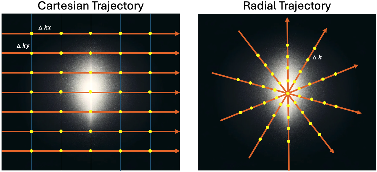
The raw MRI signal does not contain information about where in k-space each measurement was taken. It only contains nSamp complex-valued values. To reconstruct an image accurately, we must know the spatial k-space location of each sample. This sampling pattern is referred to as the trajectory.
In Monalisa, a trajectory is represented as a double-precision array:
t % size [frDim, nPt]
Each column of t corresponds to a single k-space point (sample), and each row corresponds to a spatial dimension (e.g., kx, ky, kz).
Note
All trajectories must be defined in physical units, consistent with the scanner’s true input Field of View (FoV). We do not support arbitrary units (e.g., [-0.5, 0.5] unit cube).
Example: Let’s say your acquisition FoV is [200, 300] mm. Then:
The step size along kx must be 1 / 200 (in 1/mm)
The step size along ky must be 1 / 300 (in 1/mm)
Similarly, for a radial trajectory with FoV of [360, 360] mm, the spacing between points on each spoke must be 1 / 360.
Monalisa provides a selector function to generate standard trajectories:
t = bmTraj(mriAcquisitionNode)
This function supports various predefined trajectories, including those extracted directly from PulSeq .seq files. This allows easy integration of vendor-neutral sequence designs into Monalisa reconstructions.
However, please note:
Warning
Even when using the same nominal trajectory (e.g., radial), different sequence implementations or vendors may produce slightly different actual coordinate sets. Always verify that the trajectory used in reconstruction matches the one used during acquisition.
Custom Trajectories
You may provide a custom trajectory, but coordinates must be in physical units matching the true acquisition FoV (e.g., 1/mm).
For instance, if you have a trajectory defined in a unit cube (e.g., scaled between -0.5 and +0.5), you can rescale it with:
Where:
\(aN_x, aN_y, aN_z\) = matrix size in each direction (e.g., 256 × 256)
\(aL_x, aL_y, aL_z\) = true FoV in each direction (in mm)
Alternatively, if your trajectory is scaled from -aN/2 to aN/2 - 1, apply:
Need More Help?